Address
304 North Cardinal
St. Dorchester Center, MA 02124
Work Hours
Monday to Friday: 7AM - 7PM
Weekend: 10AM - 5PM
Precision cold-rolled stainless steel strip, coil and belt solutions
Address
304 North Cardinal
St. Dorchester Center, MA 02124
Work Hours
Monday to Friday: 7AM - 7PM
Weekend: 10AM - 5PM

A practical troubleshooting framework for burr and edge quality in precision stainless steel slitting.
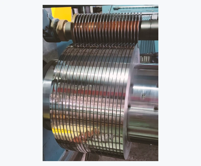
Stainless steel slitting burr is a system result, not a single machine fault. Knife clearance, lateral load, strip tension, material temper, edge support and winding all influence how the metal separates. Changing one setting may reduce burr while creating a wavy edge, loose coil or unstable slit width somewhere else.
This guide explains what the burr reveals, how to separate process causes from material causes and which measurements make acceptance repeatable.
During shear slitting, the strip is deformed by opposing tool edges. A normal section can show rollover, a burnished shear zone, a rougher fracture zone and a burr. The proportions change with knife condition, clearance, material ductility and the amount of support around the cutting point.
A burr is therefore tied to the separation mechanism. Simply adding a deburring step can hide the symptom, but excessive clearance or poor overlap may still leave microcracks, edge work-hardening or inconsistent edge width that affect forming and fatigue.
| Variable | What can go wrong | Practical review |
|---|---|---|
| Knife clearance | Too much clearance increases tearing and burr; too little can raise tool load and edge damage. | Confirm the starting value against material, thickness and temper, then verify by edge samples rather than assumption. |
| Knife overlap | Insufficient overlap can leave an incomplete cut; excess overlap changes edge deformation. | Record setup by material and gauge and inspect for a consistent burr side. |
| Knife condition | Nicks, wear and mismatched tool edges transfer directly into the strip. | Inspect blades, use a microscope, and replace as a matched set where required. |
| Lateral load | Side load can create a primary burr on one side and secondary slivers on the other. | Check guide alignment, spacer condition and strip tracking. |
| Tension | Low tension causes edge wave; high tension can narrow or mark the strip. | Set tension for gauge, width and coil build and verify across the run. |
| Material temper | Harder, work-hardened strip behaves differently from annealed strip. | Record grade, temper, tensile target and master-coil history. |
| Master-coil condition | Camber, crossbow, edge crack or slitter burr can transfer into the finished strip. | Inspect incoming coil edges and trim allowance before narrow slitting. |
| Winding | Poor layer alignment can bruise an acceptable edge after cutting. | Control tension taper, guide position and interleaving. |
Published clearance ranges are useful for setting up a trial, but they cannot replace a material-specific procedure. Stainless grades differ in work hardening, ductility and springback. Thin strip, narrow width and high-hardness tempers reduce the tolerance for setup variation.
A practical approach is to hold material and tooling constant, run a small matrix of settings and classify the edge at magnification. Measure burr height, burr direction, edge wave and width. Avoid selecting the setup from burr alone; a low-burr setup with unstable width or heavy slivers is not a production solution.
The consequence determines the acceptance method. A visible burr limit may be enough for a covered structural part. A fatigue or sealing edge may require a profile check and downstream trial.
Start with a drawing that identifies the permitted burr side. Measure burr height at representative locations across the coil length and both edges. Record width, edge wave and crossbow at the same time so a narrow strip is not judged by one attribute.
For critical edges, use magnification or a profile reference to classify rollover, burr and any nicks. Keep a first-article sample for each material, thickness and setup family. Recheck after knife changes, coil-source changes or a shift in temper.
| Observation | Likely direction | Do not overlook |
|---|---|---|
| Heavy continuous burr on one face | Clearance, overlap or lateral load mismatch. | Burr side may indicate which knife set or spacer is out of position. |
| Intermittent slivers | Knife nick, damaged spacer or strip edge defect. | Inspect the master coil before changing every machine setting. |
| Edge wave with acceptable burr | Tension, width ratio, alignment or crossbow. | A burr fix can be hiding a tension problem. |
| Width drifts along the coil | Springback, knife load, guide movement or coil condition. | Measure the edge after winding as well as immediately after slitting. |
| Edge looks clean but fails forming | Micro-burr, work hardening or edge microcrack. | Visual gloss is not a fatigue or forming test. |
The strongest control is a defined process family. Use the same material grade, temper and thickness grouping; record knife setup; verify width; and compare the edge photograph or measurement before the next order. A stainless steel slitting burr that changes between otherwise similar lots is evidence that either the material condition or the process setup has moved, so investigate both before releasing the next coil.
Deburring is a finishing operation that can improve handling and downstream safety, but it should not conceal unstable slitting. Define the incoming slit edge first, then select a round edge, chamfer or light break where the application benefits from geometry change. Compare deburred 304L stainless strip, square edge 301 spring strip and round edge 316L stainless strip to see how the edge requirement changes the product specification.
Read the related steel strip edge finishing guide or the existing article on setting a practical strip burr limit.
For related standards terminology, use the applicable ASTM International or ISO material and dimensional standard rather than a generic shop note.
