Address
304 North Cardinal
St. Dorchester Center, MA 02124
Work Hours
Monday to Friday: 7AM - 7PM
Weekend: 10AM - 5PM
Precision cold-rolled stainless steel strip, coil and belt solutions
Address
304 North Cardinal
St. Dorchester Center, MA 02124
Work Hours
Monday to Friday: 7AM - 7PM
Weekend: 10AM - 5PM

A practical engineering guide to steel strip edge geometry, process selection, specification and inspection.
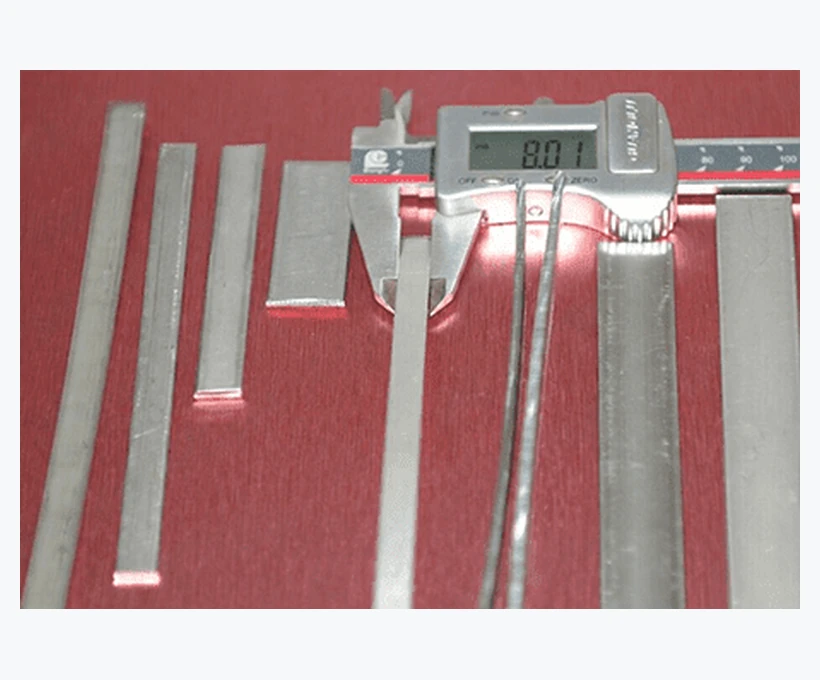
Steel strip edge finishing changes more than appearance. A square edge, a small corner break, a full radius and a deburred edge create different contact stresses, tooling loads, sealing behavior and inspection requirements. For buyers and product engineers, the useful question is not simply “round or square?” but which edge geometry keeps the finished component stable through its next process.
The same slit strip can perform differently in a progressive die, a flexible seal, a welded subassembly or a high-cycle spring. The edge is where thickness, material structure and forming history meet. Controlling that edge begins with a clear drawing and a process review.
Slitting separates one wide coil into narrower coils. The edge left by that operation can include rollover, a shear band, a fracture zone and a burr on one side. Deburring or reshaping changes the resulting corner but does not erase the material history.
Edge finishing is therefore defined by geometry, direction and measurable limits. Two strips can both be described as “deburred” while one retains a near-square corner and the other has a visible radius or chamfer. Those are not interchangeable in a drawing.
| Edge form | Effect | Common fit | Main risk |
|---|---|---|---|
| Slit square edge | Preserves section width and a defined corner, usually with a controlled burr side. | Contacts, clips and parts where the corner is part of the assembly geometry. | Sharp contact, burr transfer and guide wear. |
| Deburred square edge | Removes loose or projecting burr while keeping a relatively square profile. | General stamping, electrical parts and improved manual handling. | Residual micro-burr or an edge break that is not defined dimensionally. |
| Round edge | Spreads contact and reduces a sharp stress raiser; often improves sliding and seal contact. | Medical, food, chemical, wear-sensitive and fatigue-sensitive parts. | Removal can change width or contact area; inadequate radius control causes variation. |
| Single chamfer | Breaks one corner while retaining a flat land on the other face. | Parts that seal or contact on one side only. | Orientation error; chamfer placed on the wrong face. |
| Double chamfer | Breaks both corners while retaining a central flat land. | Visible edges, assembly guidance and controlled insertion. | Loss of section and extra handling sensitivity. |
A radius removes the sharp corner that can concentrate stress in bending or fatigue. It can also reduce scratching and guide wear when strip slides across a surface. In seals and packaging equipment, a smoother edge may lower the chance of cutting a polymer or creating a leak path.
However, a radius is not automatically better. It can reduce the flat contact area needed for a terminal, alter weld fit-up or make edge width difficult to verify. Very thin strip has little material available for reshaping, and an aggressive radius can create a knife-like feather edge if the process is not controlled.
Specify the edge by function. State whether the interface is static or sliding, whether a seal touches the strip, whether the edge is welded and which direction the strip is bent. A radius that helps a sliding guide may be wrong for a contact that relies on a crisp shoulder.
A square edge is often used where the slit side provides a locating face, a stop, a contact width or a weld preparation. The objective is to remove loose burr without destroying that geometry. The burr side should be specified because flipping a coil can change which surface contacts a guide or die.
A chamfer is a compromise: it removes one or both sharp corners while preserving a central flat. Single-side chamfering is useful when one face is cosmetic or receives a seal and the opposite face must remain square. Double chamfering can support easier insertion or safer manual handling. As with a radius, edge orientation must be controlled.
| Downstream process | Start with | Questions to resolve |
|---|---|---|
| Progressive stamping | Deburred square or small corner break | Burr face, feed direction, die clearance and coating protection. |
| Sliding or guiding | Round edge or controlled chamfer | Contact pressure, guide material, surface finish and wear allowance. |
| Sealing or gasketing | Round edge after seal trial | Seal hardness, compression and whether the edge is stationary or moving. |
| Welding | Deburred edge with defined land | Fit-up, heat input, oxide removal and required weld toe. |
| Visible appliance or automotive trim | Chamfer or radius with finish protection | Viewing direction, touch exposure, coating and handling protection. |
| Spring or flexure | Round edge after fatigue review | Bend direction, stress amplitude, surface defects and edge orientation. |
A useful edge callout makes both shape and acceptance unambiguous. Include a magnified section sketch, the burr limit, the face on which burr is permitted and the edge radius or chamfer with a tolerance. Add the measurement method and sampling frequency to the inspection plan.
For coils, also define whether the burr side must remain consistently up or down as wound. If the edge orientation is not controlled, downstream automation can see a different contact condition from one coil to the next even when width is correct.
Visual inspection catches gross burr, laps and edge damage, but it does not quantify a fatigue-critical radius or a small residual burr. Optical measurement, a profile projector or a suitable stylus can record edge geometry. Burr height can be sampled against a magnification reference. For strip that will be coated or handled, a tape or wipe test may reveal loose particles that a dimension check misses.
Coil-level checks should also include width across the length, edge waviness, crossbow, layer alignment and the consistency of which face carries the burr. If the part is later bent or heat treated, approve the edge in the finished condition whenever possible.
Steel strip edge finishing works best when the supplier knows the first production operation. A clean-looking edge is not a complete specification. The useful release condition combines a defined profile, a measurable burr limit, consistent orientation and a package that protects the edge during transport.
Review related options such as round edge 316L stainless strip, chamfered 430 stainless strip and deburred 304L stainless strip. Existing guidance on setting a practical burr limit can help connect the drawing to inspection.
For terminology and material context, refer to World Stainless, ASTM International and the applicable product standard.
